Version 2.40 of my SatNav software and the compact hardware unit with just an OLED display meant I could stop trying to fix things that were still unfinished. I had full battery management, conditional data logging, robust and error-tolerant data downloading on demand and power management that avoided any SD card corruption.
Where next?
There were things still unfinished: I wanted the unit to be able to use WiFi to transmit data instead of making do with manual downloads to a USB pen drive; I would have liked to remove the code which drives a liquid ink display (Papirus) into a more general purpose module, where it should be, but had never tried writing one. RiscBASIC could compile an application to a module but only at 26 bit. Both these aspirations were therefore not immediate.
It was not long before an idea came to me: as usual it hit me at 0400. Putting detail aside, the unit’s fundamental purpose was to monitor incoming data (GPS data) and selectively log the data along with time and date of receipt. The data could then be downloaded on demand to a USB pen drive in an appropriate format. My university training had strongly counselled me never to press something designed for a specific task into service for a quite different purpose. At least not without careful thought.
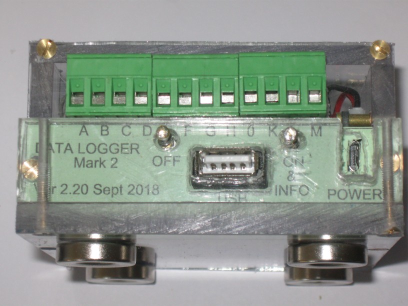
The front panel showing the push buttons and the USB socket, as well as the 12-way screw terminal block, which can easily be unplugged.
The idea I got was that I could build a data monitor which would examine a number of input lines and log any state change. The inspiration for this came from my volunteer work on the Severn Valley Railway: we had experienced a few faults on S&T equipment that had proved very difficult to fault find. They were intermittent and on complex equipment where faults would be difficult for the signalman to report in a way that could help us diagnose the problem. Accurate details of exactly what had occurred would help enormously.
Removing the GPS module (which used the serial port to communicate), adding a CJE real time clock module and using the GPIO pins to monitor incoming data would mean that very little in the SatNav programme would need to be altered to fulfil this new purpose.
Data Logger
The main purpose of the data logger is to monitor signalling circuits so that a precise sequence of relay operations can be logged. Eight inputs are scanned 1500 times a second and any changes of state are logged. The GPS module has gone, replaced by a simple real time clock card. Otherwise the software is very similar, with changes of state of any one of the eight inputs being the parameter that is being monitored rather than GPS location. The unit is designed to operate for weeks at a time, with regular visits to download data to a USB pen drive simply by pressing the 'ON & INFO' button. Making the device fault tolerant was quite tricky as there is no desktop display to show errors. (A desktop display is being created but no monitor is plugged in.)
The GPIO inputs themselves on the Raspberry Pi used 3.3V logic and had software-controlled pull-up or pull-down resistors. The circuits being monitored used 12V, 24V or 50V and comprised a number of relay contacts in series with a relay coil. Some relays had spare contacts (making them easy to monitor) but some did not, particularly those monitoring track circuits.
The ‘simple’ DC track circuit exploits the hysteresis of the relay so that it falls away at a known voltage and requires a higher voltage to pick up again when the train has gone. Monitoring the single contact provided is the only way which means breaking into signalling circuits without disturbing them.

The signalling circuit shown is a 24V circuit with the fused positive supply (B12fx) on the left and the negative return (N12) on the right. Inputs A to D are ‘active low’ and connected to GPIO pins GP5-GP8 which have, by default, pull-up resistors on chip. Inputs E to H are ‘active high’ and are connected to GPIO pins 17-19 and 23 with pull-down resistors.
That also means being tolerant of relay back EMFs as the relay coil circuit is broken. How resilient the unit will be in service is still unproven.

My first stab at protecting the GPIO 3.3V logic from the 24V signalling supplies and the hundreds of volts that might appear as relay coil circuits are broken. Each input is inactive when open circuit and can be activated in the voltage ranges noted. This gives a choice of +1 to -30V (which includes 0V); -6 to -30V (with a series resistor and excludes 0V) or +6 to +30V. Voltages in the range specified will make the input ‘active’.
Monitoring of the inputs has a ‘test’ mode built in so that holding down certain keys on the keyboard will toggle the measured status of the particular input.
Construction
The case itself is made from polycarbonate sheet, cut to several different widths by the supplier that I cut to length with a hacksaw.
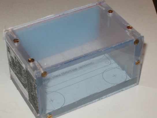
The case with printed labels stuck onto the protective film after cutting the ploycarbonate sheets to size.
Most of the breakout circuit board is taken up with the various components needed to protect the GPIO inputs from harmful external voltages but otherwise it is a very similar layout to that used for the GPS unit. Circuitry to control power switching is identical.

Internal wiring. Signal diodes, 1N914, resistors and capacitors should protect the 3.3V level logic from +24V and relay coil back EMFs. Inputs will sink no more than 200µA to avoid disturbing the signalling circuits being monitored.

A side view shows the plug-in screw terminal block which can be connected to the circuits to be monitored using up to 2.5mm2 cable.
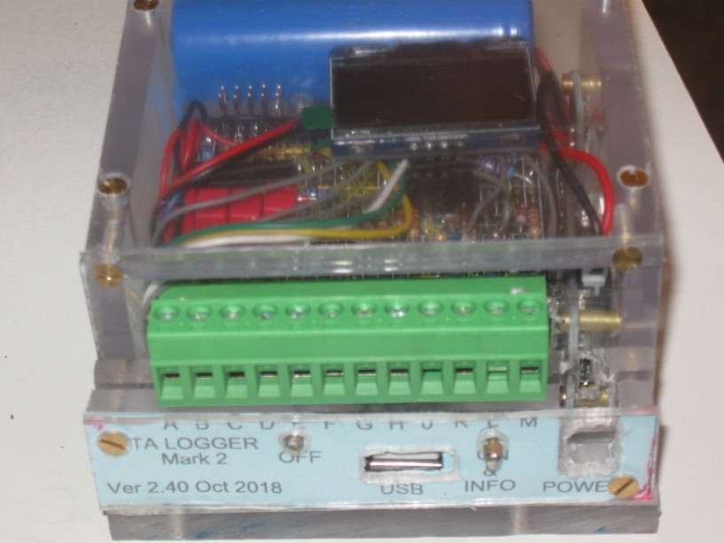
Eight inputs plus three voltage-measuring inputs (approx. 0 to 30V with a resolution of 33mV). The terminal block can be unplugged.
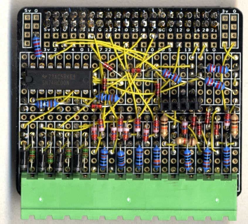
All I have to do now is to check for any dry soldered joints!
Testing
Power consumption is about 150mA but the unit is designed to operate with an external mains power supply. The internal battery allows it to continue monitoring the signalling circuits for 17 hours after external power is lost. The signalling circuits themselves are also battery backed.
The unit has an ADC board with three spare voltage inputs, allowing any positive voltage to be recorded at any state change.
The OLED display shows the time of day and the status of the eight inputs and the three voltages (plus the supply voltage, which is the battery voltage unless it is being charged by a healthy external supply.
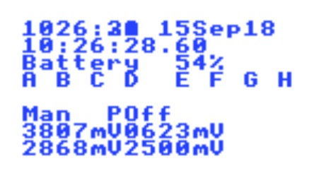
The OLED display shows the time (in GMT) updating once per second on the first line and shows the exact time of the last log entry on the second line with the status of each input as logged. On the line below the letters A to H will appear an ‘X’ if that item is active. The line showing ‘Man Poff’ indicated that the unit was switched on manually with no external power and that was the last change of state (an ‘A’ would mean A went active and ‘a’ inactive). The four voltages are those measured at that time. 3.807V implies 54% battery life. The other voltage inputs are not connected.

An analysis of the sampling shows that the sample interval is about 650µs (pink dots) while ‘lost time’ (for example to update the OLED display - 8cs - or to measure voltages - 5cs) is generally less than 12cs.
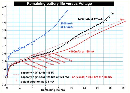
The battery should last about 18 hours (at 175mA) and the voltage reading can be used to indicate the battery life remaining, as above.
Routine observations
The OLED display shows the current time and date in Grenwich Mean Time as well as the last occasion (time only, but shown to the nearest hundredth of a second) when one of the eight inputs being monitored changed state. The status of each input (A to H) is also shown.
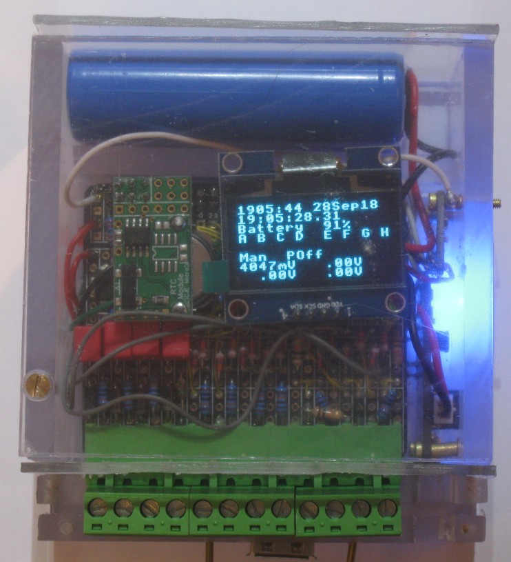
No inputs are connected so the unit shows the initial condition: manually turned on with no external power supply.
Logging
The unit will keep a log of the various inputs monitored (making a new entry at each state change or every 30 minutes) which can be downloaded onto a USB pen drive on demand by inserting a USB pen drive in the USB socket and pressing the ‘ON & INFO’ push button.
Download request at &573EC486
Opening file for day 60 as SCSI::0.$.Lg28-09-2018/csv
Closing file for day 60 length=50173
Writing valid lines from DataLog/csv (length=C457) to
.RL28Sep2018/csv
Closing copy file at length=50263
Reopening copy file from 57 to C457
Logfile now truncated to length=C400
When a log is downloaded, the daily log files are written to the pen drive along with a file (shown above ‘LogFile.csv’) which will show detailed information to allow any errors to be followed up.
Pressing the ‘INFO’ button will bring up this screen and show the progress of the download as shown. The ‘ON’ button is used to ensure the messages don’t disappear.

The ‘ON’ button is used to make sure that the messages remain on screen for long enough for the user to read them.

As each day’s log details are downloaded, a progress report is shown.

If the process completes with no errors this screen is shown

Releasing the ‘ON’ button confirms you have read the message.
Logging format
The logging of the inputs uses a ‘CSV’ file, the syntax of which includes the time of each entry and the various parameters being monitored. The logging now looks like the example below.
28-09-2018,11:29:34.71,&573E97E7FF,0,0,0,0,0,0,0,0,4593mV,04.98V, .00V, .00V,Man POn ,0
28-09-2018,11:29:49.57,&573E97EDCD,0,0,1,0,0,0,0,0,4587mV,04.98V, .00V, .00V,C,21675
28-09-2018,11:29:49.84,&573E97EDE8,0,0,0,0,0,0,0,0,4596mV,04.98V, .00V, .00V,c,238
28-09-2018,11:30:52.50,&573E980662,0,0,1,0,0,0,0,0,4593mV,04.98V, .00V, .00V,C,92043
28-09-2018,11:30:52.71,&573E980677,0,0,0,0,0,0,0,0,4596mV,04.98V, .00V, .00V,c,0
28-09-2018,11:31:29.20,&573E9814B8,0,0,1,0,0,0,0,0,4596mV, .00V,05.04V, .00V,C,53452
28-09-2018,11:31:31.42,&573E981596,0,0,0,0,0,0,0,0,4596mV, .00V,05.04V, .00V,c,3104
28-09-2018,11:33:46.94,&573E984A86,0,0,0,0,0,0,0,0,0000mV, 0.00V, 0.00V, 0.00V,Quit,0
A download request will copy a log file for each of the last 60 days for which data are available onto a USB pen drive. It will archive previous days’ log entries as a record of what was extracted. Subsequent downloads will thus still capture full data for the current date. The example above shows log entries created by touching input ‘C’ with a wire connected to 0V with 5V applied to K or L. Times are in GMT.
Performing a log download
Place a USB pen drive in the USB socket, wait a few seconds for the presence of the drive to be recognised by the operating system and then press the ‘ON & INFO’ button. Log entries up to and including the current day will be downloaded, the data for the last 60 days being placed in separate files on the USB stick. Progress of the download will be shown on the OLED display and once reported complete the USB pen drive should be removed and the ‘ON & INFO’ button used to confirm this has been done, as prompted.
If an error message is shown on the OLED display (such as ‘disc drive is empty’) this can be recorded. The date and time at which the download was carried out and the date and time shown on the OLED display should also be recorded (so that any clock drift can be recorded).
A continuous log is stored on the internal 16GB SD card and historical data are archived on completion of any download (in case the pen drive is mislaid) with just the data for the current date retained in the accessible log.
Analysis of the data downloaded
Analysis of the data downloaded will be done in an Excel spreadsheet which will allow any abnormal operation to be examined in detail.
Logging
Daily logs are created when a download request is made, with dates, times and circuit activity recorded every 30min or at any change of state.
Power consumption
Although it cannot be seen with only an OLED display, a full desktop is being generated. With no HDMI display connected, power consumption drops from 550mA (excluding the display itself) to about 170mA so it is quite efficient.
Powerboost board
The ‘power booster’ board allows an internal 3.3V Lithium-Polymer battery to produce a 5.2V output and will use an external 5V power source to take over this rôle and charge the internal battery until fully charged. Switching on and off is controlled by an ‘ENABLE’ input.
A blue LED lights if power is being supplied to the computer. With the booster board output disabled, only a minimal current is drawn from the internal battery. A red LED lights if the internal battery becomes discharged below 3.2V (a diode is fitted to disable the output automatically). Fully discharging the internal battery is likely to damage it.
While the internal battery is being charged a yellow LED lights, turning green when it is fully charged. A small current drain to light the green LED to show a full charge seems enough to keep some power banks happy even whilst the unit is otherwise powered down.
This means the external source can be connected and disconnected without affecting the operation of the device except to extend battery life.
Analogue to digitial conversion
The ADC board is the 12 bit ADS 1015, by Adafruit, and it takes about 5cs to check all four voltages. I did try a 16 bit version but it took quite a bit longer to do the same sampling. I had also included the voltage sampling in the same block of code as that examining the eight GPIO pins for any state change. This meant that the unit was sampling at about 10Hz.
I realised that state changes of the GPIO pins needed to be monitored more frequently and voltages only really needed to be recorded at any state change. This improved the data sampling rate to 20Hz.
The next inspiration was that the OLED display was being updated each time there was a state change.
The OLED module keeps a sprite in memory which is updated line by line as text is written to the display drivers. Every so often, the display is updated via the IIC bus, which takes about 12cs.
There seemed no point in updating the OLED display more quickly than the eye could see so I held back updates if the display had been updated in the last 2s. The sampling rate rose to 1500Hz.
The Organic LED Display
The OLED display shows the active/inactive status of the eight inputs under the headings A to H under which an ‘X’ appears if the circuit concerned is active, updating every 30 mins or whenever any of the inputs changes state. The three voltages being monitored are also displayed, updating at the same time. Time and date is also shown, in GMT.
This continuous display allows the set up of the unit to be checked easily and the last recorded state change is displayed along with the precise time (to the nearest hundredth of a second) that it occurred.
Loss of power
Whilst the unit should continue operating in the event of a mains failure, it will shut down if its internal battery becomes exhausted and would, in that event, need to be restarted manually. Before doing so, the fact that mains power has been restored should be confirmed (a yellow or green LED indication on the powerboost board confirms that the internal battery is being charged).
The unit takes about 11s from power on to be functional and the real time clock is able to keep time whilst the unit is switched off by having its own 3V 70mAh coin cell. The unit will continue logging for about 17 hours after power has been removed after which it will shut down.
The ‘OFF’ button allows the unit to be shut down manually. The status of the ‘ON’ and ‘OFF’ buttons is held internally so that it can de determined which button was the last to be pressed.
Battery endurance
The internal rechargeable battery is monitored for state of charge each time any of the eight inputs changes state: it will show either ‘xx%’ (while power is off) or ‘chgng’ (whilst being charged). Below 3.2V it is discharged and the power boost board will force power off. The battery should last for 500 charge/discharge cycles.
If a keyboard, mouse and monitor are connected, then a multi-tasking graphical user interface will be displayed. Power consumption rises from 1W to about 3W with an HDMI display connected (excluding the power that the display itself requires). Direct WiFi access is not yet supported by RISC OS.
Power on/off
The ‘OFF’ button does not switch the unit off directly. Power is removed under software control so that corruption of the SD card, which could occur if power was removed whilst the log was being updated, is avoided.

Pressing the ‘OFF’ button will warn the user before removing power, as shown.
Provided that the unit has been operating for at least six seconds (enough time for the RISC OS desktop to start), the ‘off’ button will pull GPIO 26 low but do nothing else. The software will notice this, complete any logging and then do a system shutdown using the command SYS "TaskManager_Shutdown",162 which will shutdown all applications tidily and restart RISC OS. The effect of this is to update the CMOS ‘last time on’ setting and restart the ROM. As the ROM reinitialises, GPIO 4 becomes high impedance thus removing power.
Software update
A specially prepared USB pen drive may be used to update the software automatically or to extract archived data, but this is not a routine operation.
Silent errors
With a monitor using the HDMI output to display a desktop, any error that might be generated can be recorded, with its line number, and investigated. It is very frustrating to see the software ‘freeze’ and realise that an error message is being displayed but cannot be seen. If you simply plug in an HDMI display at that point, the computer will not send data to it as the HDMI system is not powered up. I therefore added an error display to the OLED drivers.
The finished unit clamps to a steel surface:
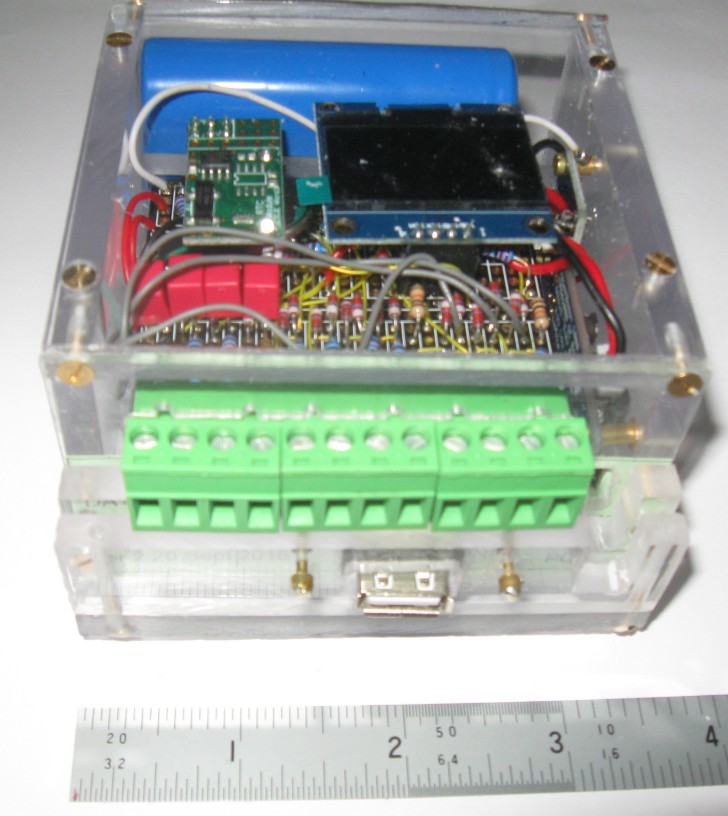
The finished unit.
